Tinted Windows: Reconstructing Historic Dithering
Table of Contents
With the capacity only to display a very limited palette at higher resolutions, Windows 3.x used dithering to create the effect of a wider range of solid colours. There are a number of standard dithering algorithms, but these don't match what Windows actually did. The specific approach is documented in U.S. Patent 5485558, but there are a number of errors in the description given there. This is the result of my reverse engineering to produce behaviour correct to the real system, and a practical implementation illustrating it. The algorithm takes three colour coordinates 0–255 for each of the red, green, and blue channels, and produces an 8x8 dither pattern containing up to four palette colours spread across it.
Background
Windows 3 was intended for use with VGA graphics cards, which supported 640x480 resolution with 16 distinct colours chosen from an 18-bit colour space. The standard Windows colour palette used white, black, and darker and lighter shades of red, green, yellow, blue, magenta, cyan, and grey.

To create the illusion of a broader range of colours, dithering would be used to mix pixels of different palette colours together to approximate the real colour.

Windows combined a selection of up to four colours drawn from 15 palette colours (light grey was excluded) to create any approximation, using an 8x8 pattern.

There are a number of standard dithering algorithms, but these give different (and generally worse) results than what Windows did, even with the same palette. There is a (now-expired) patent that describes the approach taken in Windows, but following the code given there doesn't produce matching results to the real system: wrong colours used, wrong proportions, and totally invalid for many colours.


The next section explores my reconstruction of the true algorithm and correction of the errors in the patent description to replicate actual behaviour.
The Algorithm
U.S. Patent 548555810
and . . “Method and system for displaying color on a computer output device using dithering techniques”. United States Patent 5485558. Online.The patent was filed May 22, 1990, the release date of Windows 3.0. It's long expired and worth diving into. The whole thing is relevant but I'm going to be referring to Table 14 in particular a lot, which is a C code listing of (purportedly) the algorithm in use. The code isn't the easiest to follow because it relies almost entirely on global variables for passing arguments and return values, and most of it's unnecessarily structured in terms of matrices. It's also just wrong in several places, some of which are simple syntax errors, but others are quite annoying to trace; for the patent's own running example, the code produces a pure-grey dither pattern instead of the purplish colour it is meant to replicate. It uses "pel" for pixels and "super-pel" for the 8x8 dither pattern.
The dither pattern uses 15 colours corresponding to every combination of half, full, and zero strength in each dimension, expressed as 4-bit RGBI (the 8 bit, I, makes the colour brighter). These are numbered 0-15 with 8 unused and the bits correspond directly to channels and intensity, in increasing order of significance RGBI. The patent gives these names with 8-bit values for each channel, but these would have been squashed to 6-bit for display, and on modern displays the dark colours in particular are darker than they would have appeared on contemporary monitors; the table below shows an approximation of how these shades would have looked at the time as well as swatches of the provided RGB values for all colours.
| R | G | B | IBGR | Decimal | Name |
|---|---|---|---|---|---|
| 0 | 0 | 0 | 0000 | 0 |  Black Black |
| 128 | 0 | 0 | 0001 | 1 |   Dark red Dark red |
| 0 | 128 | 0 | 0010 | 2 |   Dark green Dark green |
| 128 | 128 | 0 | 0011 | 3 |   Dark yellow Dark yellow |
| 0 | 0 | 128 | 0100 | 4 |   Dark blue Dark blue |
| 128 | 0 | 128 | 0101 | 5 |   Dark magenta Dark magenta |
| 0 | 128 | 128 | 0110 | 6 |   Dark cyan Dark cyan |
| 128 | 128 | 128 | 0111 | 7 |   Grey Grey |
| - | - | - | 1000 | 8 |  (unused) (unused) |
| 255 | 0 | 0 | 1001 | 9 |  Red Red |
| 0 | 255 | 0 | 1010 | 10 |  Green Green |
| 255 | 255 | 0 | 1011 | 11 |  Yellow Yellow |
| 0 | 0 | 255 | 1100 | 12 |  Blue Blue |
| 255 | 0 | 255 | 1101 | 13 |  Magenta Magenta |
| 0 | 255 | 255 | 1110 | 14 |  Cyan Cyan |
| 255 | 255 | 255 | 1111 | 15 |  White White |
The patent uses a working example of colour (r=128, g=31, b=190), but you can choose your own to follow along with.
Pick a colour to use.
We'll use this purple/blue colour, r = 128, g = 31, b = 190, for the rest of this article.
Mapping into tetrahedral space 0
The algorithm maps the colour coordinates into one of six tetrahedral subregions of the colour cube, using four vertices of the cube. These tetrahedrons are defined by the planes with equal values R=G, G=B, and R=G (these each cross white, black, and one other opposite pair of vertices). The tetrahedron is then divided again into four subspaces, defined by colours on the vertices. It gets into that first tetrahedron by swapping coordinates such that r >= g >= b, remembering the swaps so that they can be undone at the end. This is:
swapRB = r < b
if swapRB:
    r, b = b, r
swapGB = g < b
if swapGB:
    g, b = b, g
swapRG = r < g
if swapRG:
    r, g = g, r
The swapXY values are used later to transform colours back. For our running example, we start with (r = 128, g = 31, b = 190), so swapRB is true, swapGB is true, and swapRG is false, and for the rest of the algorithm the three values are (r = 190, g = 128, b = 31). They will be swapped back at the end.
Finding the subspace
The subspace is determined by inspecting the coordinates. The ComputeSubspace function in the patent code is written very opaquely, but what it comes down to is:
- You're in subspace 0 if r < 128; or
- You're in subspace 1 if r + g < 256; or
- You're in subspace 2 if r + b < 256; or
- You're in subspace 3 otherwise.
For the running example, we're thus in subspace 2.
Remembering that the values are ordered r ≥ g ≥ b, this subspace calculation is essentially "how bright is this colour".
Determining the vertex colours
The four colours to use are the vertices of the subspace tetrahedron. Every subspace contains grey (the centre of the overall colour cube) and three others from those included in tetrahedral space 0. Subspace 0 is all dark colours, subspace 3 is all bright colours, and the others are in between.
- Subspace 0 uses colours 3, 0, 1, 7
- Subspace 1 uses colours 3, 1, 9, 7
- Subspace 2 uses colours 3, 9, 11, 7
- Subspace 3 uses colours 9, 7, 11, 15
This corrects subspaces 0–2 from the patent code, which lists colour 2 instead of 3 (table 3 has them correct). For the example, the colour values are 3, 9, 11, and 7. Remember, these are the colours as reflected into space 0 at the start, not the final dither colours.
Scaling the values
Every colour coordinate is scaled down from 0-255 to 0-64 inclusive, with 255 going to 64, 251-254 to 63, and 0-2 going to 0, which isn't quite the 6-bit mapping you'd expect. The calculation is ((n / 2) + (n % 2) / 2, or more straightforwardly the first division rounds up rather than truncating.
r = floor(ceil(r / 2) / 2)
g = floor(ceil(g / 2) / 2)
b = floor(ceil(b / 2) / 2)
The example's scaled-down coordinates are r = 47, g = 32, b = 8.
Transforming the coordinates
Next, a coordinate transformation and inner product is used to calculate the number of pixels that will be in each colour. The coordinates are transformed by the origin of the subspace, which is (64, 0, 0) for subspace 3 and (32, 32, 0) in the others. The net effect is that in subspace 3 the calculation uses r - 64 and in the others it uses r - 32 and g - 32. These transformed values are multiplied by values from a matrix to calculate three counts, but the matrix from the code listing has some incorrect values. The code also mixes up its tempB and tempG variables. The corrected and simplified calculations are
- In subspace 0:
c1 = (r - 32) * -2 c2 = 2 * (r - 32) - 2 * (g - 32) c3 = b * 2 - In subspace 1:
c1 = (r - 32) * -2 - 2 * (g - 32) c2 = (r - 32) * 2 c3 = b * 2 - In subspace 2:
c1 = r - g c2 = r + g - 64 c3 = b * 2 - In subspace 3, which isn't correct either in the patent code or in the mathematics of table 5, so you have to figure it out by fiddling:
The patent would havec1 = (r - 64) * -2 c2 = g - b c3 = r + b - 64c3 = r + g + b - 64, which gives out-of-range results for bright colours and just wrong ones for the rest.
For the example, in subspace 2, the result is c1 = 15, c2 = 15, c3 = 16.
Pixel counts
These computed values determine the number of pixels for each specific colour. There can be between one and four colours with pixels allocated to them. A table of (colour, count) pairs is calculated as:
- If c1 + c2 + c3 < 64, the first colour from the list gets 64 - c1 - c2 - c3 pixels, otherwise 0.
- The other three colours are assigned c1, c2, c3 pixels respectively.
In the example, 15 + 15 + 16 = 46, so there are 18 pixels assigned to colour 3, 15 to 9, 15 to 11, and 16 to 7.
| Colour | Count | Bit pattern |
|---|---|---|
| 3 | 18 | 0011 |
| 9 | 15 | 1001 |
| 11 | 15 | 1011 |
| 7 | 16 | 0111 |
Projecting these pseudo-colours back
These "colours" aren't the ones used for the final dithering output, however: instead, their bits are permuted according to the three "swap" operations determined earlier.
For each colour:
- R corresponds to the 1 bit of the colour.
- G corresponds to the 2 bit of the colour.
- B corresponds to the 4 bit of the colour.
- I corresponds to the 8 bit of the colour.
The SwapRG/SwapGB/SwapRB values chosen at the start are now used to rearrange these, in that order. That is, these actually correspond to swapping the low two bits, the 2 & 4 bits, or the 1 & 4 bits respectively, to match when the numeric red/green/blue channels were swapped at the start. The 8 bit is left as it is.
if swapRG:
    R, G = G, R
if swapGB:
    G, B = B, G
if swapRB:
    R, B = B, R
colour = R + G * 2 + B * 4 + I * 8
Since the example has swapRG = false, swapGB = true, and swapRB = true, the calculation runs like this:
| Old | I (8) | B (4) | G (2) | R (1) | New | Count | Colour |
|---|---|---|---|---|---|---|---|
| 0011 | 0 | 0 | 1 | 1 | 0101 | 18 | 5 |
| 1001 | 1 | 0 | 0 | 1 | 1100 | 15 | 12 |
| 1011 | 1 | 0 | 1 | 1 | 1101 | 15 | 13 |
| 0111 | 0 | 1 | 1 | 1 | 0111 | 16 | 7 |
These are now the palette colours for the final dither pattern. The table has the same counts corresponding to the new colours.
Sorting the colours by decreasing darkness
The table is then sorted according to a predefined ordering of darkness, with the darkest first. The colours ultimately sort into this order:
- 0
- 4
- 1
- 2
- 5
- 6
- 3
- 7
- 12
- 9
- 10
- 13
- 14
- 11
- 15
That is, dark blue is earlier and dark yellow is later, and the same with intense blue and intense yellow.
The patent body has a table of the sorted elements for its example, but it's in the wrong order and has the wrong counts. If you skip this step entirely, the end result looks pretty much as good of a match to the target colour; this Stack Exchange answer suggests the ordering (presumably combined with the specific Bayer matrix below) is to avoid discontinuities when transitioning between nearby colours in different (sub)spaces, but I haven't found any confirmation of that. In any case, to match the expected behaviour it's necessary.
For our example, the final order should be:
| Colour | Count |
|---|---|
| 5 | 18 |
| 7 | 16 |
| 12 | 15 |
| 13 | 15 |
Filling the pattern
Finally, the 8x8 grid is filled with the chosen colours. Each colour appears as many times as its calculated count, spread throughout the pattern according to a pre-determined Bayer matrix. The matrix of allocation orders^ is given as:
This corresponds to filling in position (x, y) in this order:
[
    (0, 0), (4, 4), (4, 0), (0, 4),
    (2, 2), (6, 6), (6, 2), (2, 6),
    (2, 0), (6, 4), (6, 0), (2, 4),
    (0, 2), (4, 6), (4, 2), (0, 6),
    (1, 1), (5, 5), (5, 1), (1, 5),
    (3, 3), (7, 7), (7, 3), (3, 7),
    (3, 1), (7, 5), (7, 1), (3, 5),
    (1, 3), (5, 7), (5, 3), (1, 7),
    (1, 0), (5, 4), (5, 0), (1, 4),
    (3, 2), (7, 6), (7, 2), (3, 6),
    (3, 0), (7, 4), (7, 0), (3, 4),
    (1, 2), (5, 6), (5, 2), (1, 6),
    (0, 1), (4, 5), (4, 1), (0, 5),
    (2, 3), (6, 7), (6, 3), (2, 7),
    (2, 1), (6, 5), (6, 1), (2, 5),
    (0, 3), (4, 7), (4, 3), (0, 7)
]
Each colour gets as many pixels as the count calculated in the colour count table, assigned in that order. For the example, that's a final pattern of:
  5   7   5  12   5  12   5  12
 12   5  13   7  13   7  13   7
  5  12   5  12   5  12   5  12
 13   7  13   7  13   7  13   7
  5  12   5  12   5   7   5  12
 13   7  13   7  13   5  13   7
  5  12   5  12   5  12   5  12
 13   7  13   7  13   7  13   7
The final pattern, compared to the solid colour, looks like this:

It's mostly a pretty good match, though certainly more so on modern high-resolution displays.
Example colours to try from every (sub)space
| Swap | Subspace | R | G | B | Use | ||
|---|---|---|---|---|---|---|---|
| RB | GB | RG | |||||
| 0 | 122 | 107 | 97 | ||||
| 1 | 222 | 20 | 14 | ||||
| 2 | 179 | 158 | 6 | ||||
| 3 | 222 | 179 | 80 | ||||
| Y | 0 | 52 | 106 | 43 | |||
| Y | 1 | 25 | 144 | 12 | |||
| Y | 2 | 125 | 231 | 1 | |||
| Y | 3 | 199 | 248 | 119 | |||
| Y | 0 | 127 | 45 | 87 | |||
| Y | 1 | 156 | 12 | 44 | |||
| Y | 2 | 239 | 13 | 105 | |||
| Y | 3 | 236 | 115 | 219 | |||
| Y | 0 | 55 | 66 | 117 | |||
| Y | 1 | 8 | 22 | 165 | |||
| Y | 2 | 83 | 122 | 160 | |||
| Y | 3 | 57 | 200 | 211 | |||
| Y | Y | 0 | 46 | 126 | 69 | ||
| Y | Y | 1 | 5 | 157 | 35 | ||
| Y | Y | 2 | 95 | 156 | 106 | ||
| Y | Y | 3 | 79 | 241 | 237 | ||
| Y | Y | 0 | 11 | 7 | 71 | ||
| Y | Y | 1 | 89 | 52 | 138 | ||
| Y | Y | 2 | 99 | 17 | 178 | ||
| Y | Y | 3 | 132 | 115 | 177 | ||
| Current | |||||||
Implementation
I built a web-based tool for calculating and displaying these patterns that should run in any recent browser.
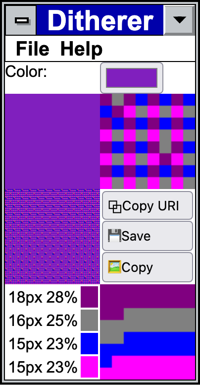
The library behind it is also available:
It tries to tread the line between paralleling the patent's code — matching the function names and structure — and being understandable. It's reasonably heavily commented.
While putting this article together I also built a (much-less-tested) Python version that's available for what it is:
The HTML version of this article also has a live implementation backing the running interactive example.
Endnotes
References
- and . . “Method and system for displaying color on a computer output device using dithering techniques”. United States Patent 5485558. Online.